Motor Control on a Low-Cost MCU
Overview
MindMotion designs its own MM32 microcontrollers and motor driver boards, and competes with ST by offering lower prices and customized support. The trade-off for customers is the development experience: there is no graphical configuration tool like STM32CubeMX and far less open-source community material, so getting a motor spinning takes more digging through datasheets and example code.
My internship had two goals: first, learn the company's motor control stack well enough to run FOC on its reference kit; then design hardware to test whether an even cheaper, entry-level MM32 part could drive a motor too.
What I did
1. Bringing up FOC on the Motor-DK
I started with the Motor-DK development kit built around the MM32SPIN580C, MindMotion's dedicated motor-control chip built on the MM32SPIN0280 MCU (96 MHz Cortex-M0, 64 pins). With no GUI configurator, I worked from the datasheet, reference manual and vendor example projects to understand how the timer, ADC and gate driver are set up, and got the field-oriented control firmware running a BLDC motor on the board.
2. Porting motor control to the MM32G0005
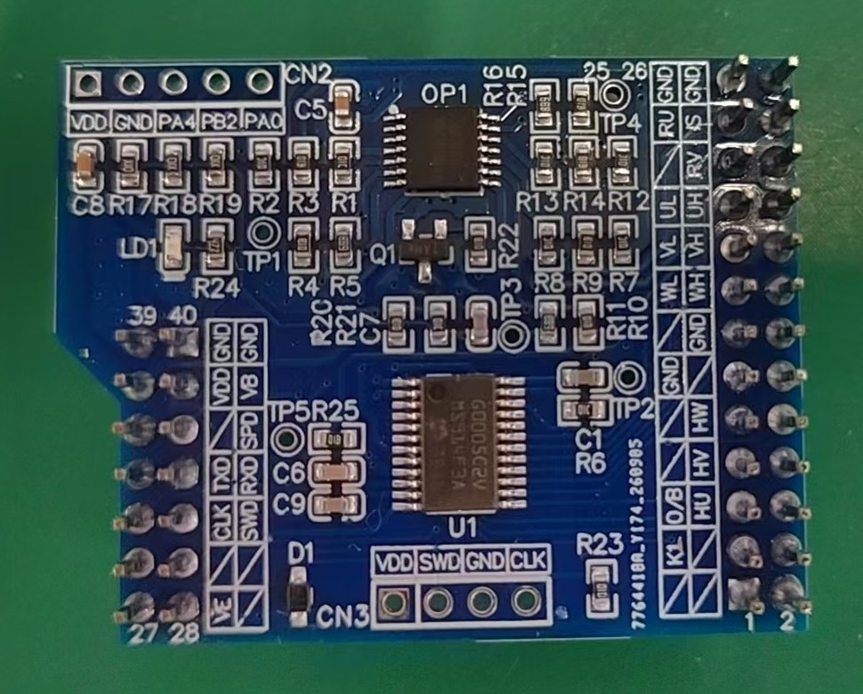
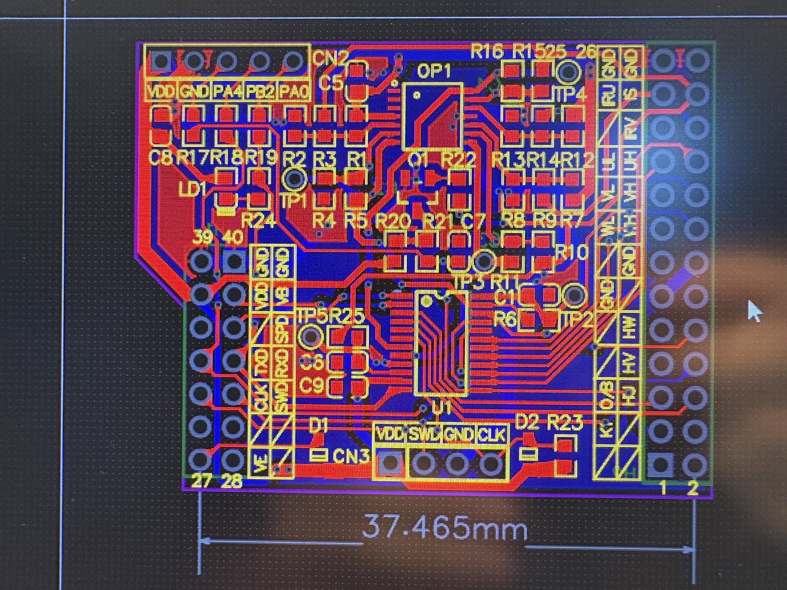
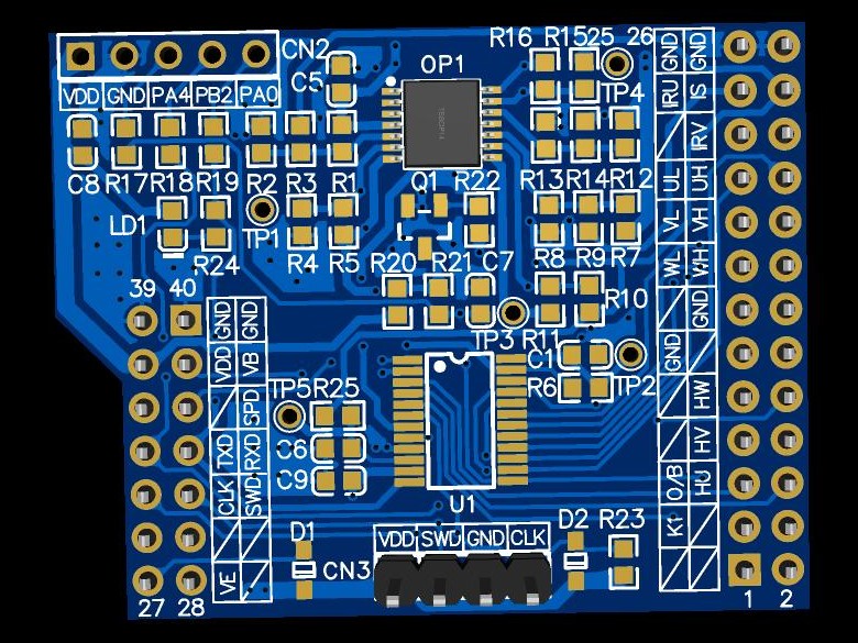
Next I moved the design to the MM32G0005, a much cheaper general-purpose MCU. I designed a small core board for it whose headers plug directly into the existing motor driver board, so the same power stage could be reused and only the controller changed.
| MM32SPIN0280 (original) | MM32G0005 (mine) | |
|---|---|---|
| Package / I/O | 64 pins / up to 57 I/O | 24 pins / 22 I/O |
| Core | Cortex-M0, 96 MHz | Cortex-M0+, 48 MHz |
| Flash / SRAM | 128 KB / 8 KB | 64 KB / 4 KB |
| ADC | 2 × 12-bit, 3 Msps | 1 × 12-bit, 1 Msps |
| On-chip op-amps | 4 | 0 |
| Advanced timers | 2 | 1 |
| Hardware divider / sqrt | Yes | No |
| Six-step PWM module | Yes | No |
The hard part was pin resources. With only 22 I/Os and a single advanced timer, whose three complementary pairs are exactly enough for a three-phase bridge, there is no slack. Each pin can only be routed to a few peripherals, and 4 of the 12 ADC-capable pins are also TIM1 PWM outputs, so a pin used for PWM is lost for current sensing. I went through the pin-multiplexing tables to find an assignment that still supports all of the required functions:
- 3-phase PWM output to drive the inverter
- Six-step (trapezoidal) commutation
- Dual-shunt current sensing for FOC
Because the G0005 has no on-chip op-amps, I added an external op-amp on the core board to amplify the shunt-resistor signals before they reach the ADC.
Results
- FOC running on the Motor-DK (MM32SPIN580C).
- Designed and fabricated a 37.5 mm plug-in MM32G0005 core board for the existing driver board, with a pin mapping that covers 3-phase PWM, six-step commutation and dual-shunt current sensing. My internship ended once the board was finished, so bring-up and motor testing on the G0005 were left for the team.